In this article I have explained a single chip circuit which can be used for recording and playing back short voice clips or any audio clip ranging from 20 to 60 seconds.
The incorporated IC APR9600 is a programmable voice recorder chip which facilitates infinite number of recording/erase of audio files in it as per user preference.
The recording or storage of the audio can be done through an integrated electret mic or via any line out or RCA port of an audio reproducing device.
However since the IC is a low bit device does not support Hi-Fi recording rather low quality music.
The sampling rate or the frequency response is limited to just 8 kHz max that's pretty ordinary if we compare it with the specs of modern Hi-Fi equipment.
Nevertheless, the IC is a stand alone device which does not depend on any external circuits, just plug it in, and it starts recording whatever voice data is fed across its input pins. Moreover since the data can be erased and refreshed any number of times, the unit becomes completely programmable and a pretty useful gadget.
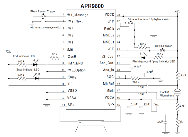
The proposed circuit of a programmable single chip voice recorder/player utilizes the IC APR9600 as the main processor of the circuit.
It's a 28 pin IC which can be very easily and quickly configured for getting the required results by adding a handful of common passive electronic components.
All the pin outs of the IC are specified by their individual functions, and the components are accordingly attached with the respective pinouts.
For example pin#28 and pin#27 are assigned as the trigger inputs for initiating playback and recording functions.
Sliding the connected switch toward right initiates the playback action while toggling it toward left puts the IC in the recording mode.
The IC also has appropriate visual indication options which provide the user with instant information regarding the position of the circuit.
The LED at pin#8 indicates the end of a playback file session.
The LED at pin#10 stays illuminated for so long the audio is being played, indicating circuit "busy"
The LED at pin#22 indicates through rapid flashes regarding the playback or recording modes of the IC.
The input data is normally picked from the mic which is appropriately connected across the pins 17 and 18 of the IC.
When the slider switch is pushed toward the recording mode, any audio entering the mic gets stored inside the IC until the specified time elapses.
The sampling rate of the IC can be set as per the user preference. Lower sampling rates will provide longer recording/playback periods and vice versa.
Longer periods would also mean lower voice quality while shorter periods of recording spec will produce relatively better sound processing and storing.
The entire circuit operates with a 5 volt supply which can be acquire through a standard 7805 IC after rectification from a standard transformer bridge capacitor network.
The audio output may be derived across pin#14 and ground which must be terminated to an audio amplifier so that the data can be heard with proper volume.
The second concept explains the functioning of the IC ISD1820 which is a single chip audio message record/playback chip featuring a 20 second audio recording and storing facility in its internal memory and playing it back through a small 8 ohm speaker whenever required.
The IC ISD1820 is a device which features a single chip audio message recording and playback facility, and is able to retain the audio message in it infinitely even while the chip in the un-powered state.
The recording-playback and erase cycles can be implemented as many as 100,000 times without any form of degradation, that’s so huge and looks almost infinite in this regard too.
The maximum recording an playback time available from this chip is no longer than 20 seconds.
The technical features of this record/playback module IC ISD1820 can be studied below:
1) Can be operated with DC 2.4V to 5.5V
2) Includes an internal audio amplifier circuitry capable of handling a 8 ohm ½ watt speaker directly at its output.
3) Works with a standard electret MIC as the input audio or voice detector.
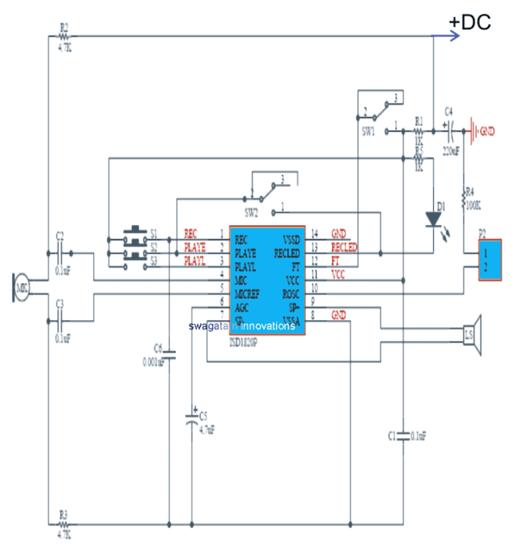
Referring to the proposed 20 second message record/playback circuit diagram using the IC ISD1820:
1) Pin#1 can be seen as the REC (recording) input pinout, which accepts a positive signal for enabling the recording function, meaning this pinout must be connected to the Vcc or the positive line while recording an audio clip,
The REC pinout has the ability to take precedence over the other pinouts marked PLAYE/PLAYL in case it is pulled high while any of the other pinouts were functioning.
Meaning suppose if any of the PLAY button was pressed, and simultaneously REC was pressed, in such case the recording (REC) will be immediately initiated terminating the PLAY action.
The voice recording action can be stopped as soon the relevant button is switched OFF, and the REC pinout is rendered at LOW. In this position an internal EOM or end of message prompt is triggered internally, causing the PLAYBACK mode to get in the ready position. This also causes the chip to go into a power down condition or in the standby condition.
2) PLAY pinouts: As can be noticed in the diagram, the IC facilitates two PLAY pinouts, which are PLAYE, and PLAYL. PLAYE allows an logic edge activated triggering, while PLAYL facilitates a logic-level activated triggering of the playback.
In the PLAY E or edge activated mode, a single press and release or a momentary press of the button will initiate the playback of the recorded clipping through the speaker, and will end as soon as the internal EOM (end of message) signal gets activated.
The PLAY L mode is activated when the attached button is pressed and held pressed without releasing it. The audio playback now continues as long as the button remains depressed, or as soon as the internal EOM is activated. Keeping the button permanently pressed will cause a higher current consumption of the IC.
Other than the REC and the PLAY buttons, this audio record/playback circuit additionally possesses a couple of switches associated with the chip in the form of SW1 and SW2. SW1 is positioned for the “Feed Through” action while SW2 for the “REPEAT” functioning. Let’s understand them in detail.
As may be witnessed, the SW1 is configured with the “FT” pinout of the IC which refers to “Feed Through”.
When actuated in the feed through mode, the signal across MIC, and the MIC_REF pinouts are bypassed through the AGC pinout of the IC, up to the the filter driver stage and finally reaching the speaker points (SP+ and SP-)
The FT input signal is responsible for controlling the feed through mode of the chip. In order to be initiated the feed through mode, the pinout FT is held at the positive Vcc logic, while the REC, and the PLAY buttons are at low logic or with their buttons in the deactivated positions.
SW2 is used for enabling the REPEAT mode, which implies that when this switch is toggled ON the playback goes on repeating the recorded message clip through the speaker non-stop, until the switch is toggled OFF.